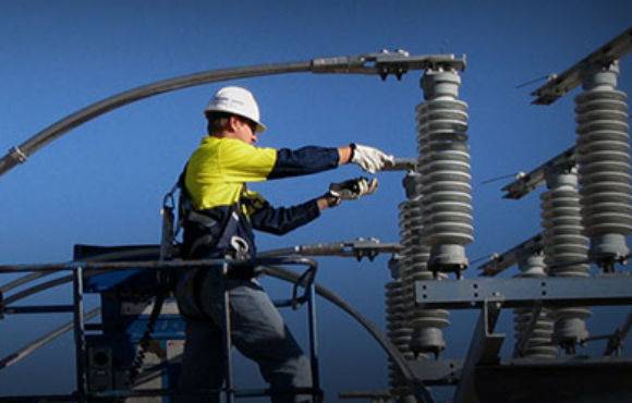
earthing design
With over 15 years of experience, there isn’t a scenario or problem that our earthing engineers haven’t come across or resolved. Be assured that your Earthing Design is in safe and capable hands.
Integral Power’s earthing designs are based on client-specific needs and are focused on protecting our clients’ personnel, assets, and operations. We use state-of-the-art earthing design software that presents complex earthing calculations in an easy-to-understand visual format. This expedites compliance and is understood by all disciplines involved in the project. The scope of our earthing system design includes the following:
- Design compliant and practical earthing systems using industry best practices and the latest software tools.
- Earth Fault current distribution modeling.
- Earth Potential Rise (EPR or GPR) calculations.
- Safety Calculations for Touch and Step voltages.
- Electromagnetic Interference & Compatibility (EMI & EMC) Studies.
- Onsite Surveys and assessments.
- Onsite Soil Resistivity Testing.
- Soil modeling and analysis.
- Post Construction Earthing Audits.
- Earthing policy formulation.
- CAD drawings of earthing layouts.
DETAIL Controls
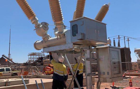
Poor earthing can lead to an increased likelihood of plant outages, process anomalies, workplace safety hazards, and fire. Components of the earthing system are prone to corrosion due to electrolytic and electrochemical processes over time. If the system has been in place long enough, the earth grid can be consumed entirely without you knowing. Facilities with sensitive electronic equipment are particularly vulnerable to disruptions due to ineffective earthing.
Our engineers will help you address your areas of concern by assessing the condition of the existing earthing and surge protection systems. Corrective actions & recommendations are provided and subsequently implemented to improve/restore the integrity of the earthing systems, helping you stay safe and compliant with all the applicable electrical codes and standards, including, AS 2067, AS/NZS 7000, AS/NZS 4853, ENA EG0, ENA EG1 and AS/NZS 3835.
Conventional high-current earth injections can disrupt plant operations. Integral Power, therefore, uses low-current injection methods wherever possible to deliver accurate data at minimal cost and inconvenience. Integral Power offers the following earth verification tests:
When current is injected into the earth system, it is met with a finite resistance which is directly dependent on the resistivity of the soil. This creates a voltage drop near the fault, called Earth Potential Rise or EPR. This EPR is directly proportional to the magnitude of the current injected into the earth and the soil resistivity. Reliable soil resistivity data around the substation is, therefore, a prerequisite to accurately modeling the performance of an earthing system.
When a fault current is injected into the earthing system, it is met with a finite resistance which creates a voltage drop around the vicinity of the fault, called Earth Potential Rise or EPR. This EPR is directly proportional to the magnitude of the current injected into the earth. A non-50Hz current is injected into the earthing system to simulate the fault conditions so that an assessment can be made of the integrity of the earthing system. The frequency is selected to avoid 50Hz interference from nearby electrical systems, and thus this testing is also called an Off Frequency current injection testing protocol.
The “touch voltage” is the difference in potential between the earthing system and any accessible metallic surface near the substation. An effective earthing system is designed to limit the touch voltage so that it does not pose any danger to anyone near the substation. The design value of the touch voltage is validated through off-frequency current injection while measuring the potential difference between the earthing system and accessible metallic surfaces in the vicinity of a high voltage substation.
The “Step voltage” is the difference in potential between any two points on the ground where a person’s feet could be positioned. It is generally assumed that a person’s step distance will not exceed 1m, and a “step voltage” is defined as the voltage difference between two earth surface points 1m apart. The design value of the step voltage is validated through off-frequency current injection while measuring the potential difference 1m apart on the ground surface around a high voltage substation.
REACH OUT TO US
Schedule a free consultation with our expert team to discuss your needs and how we can help.
intial design
Design
Preparation of Single Line Diagrams and Substation Layouts
Specifications
Preparation of Technical Specifications for all HV and LV substations equipment
Tendering
Preparation of Tender Documentation and Assistance in Technical Evaluation
Costing
Cost estimation of HV infrastructure including Capital Outlay & Lifecycle costs
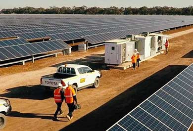
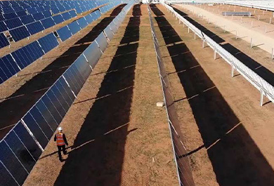
RECENT PROJECTS
From commissioning Utility-scale Renewable Generation to Mission Critical High Voltage Power networks, Integral Power has been at the forefront in the power industry, Leveraging High Voltage Expertise to create value for customers.